ArduinoNote List-pagePREVIOUS: Note8 - WebServer controlled LED DemoWeb Server controlled LED Sketch
[code lang=cpp]
/*
Web Server
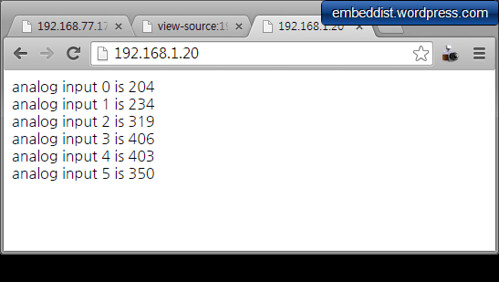
A simple web server that shows the value of the analog input pins.
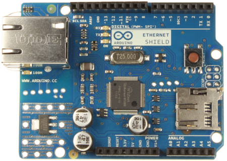
using an Arduino Wiznet Ethernet shield.
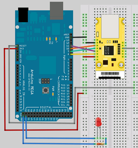
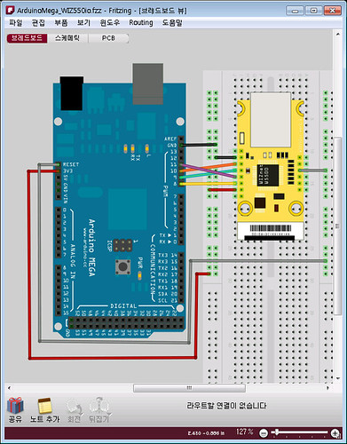
Circuit:
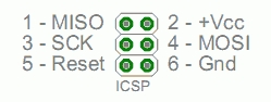
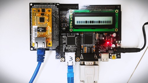
* Ethernet shield attached to pins 10, 11, 12, 13
* Analog inputs attached to pins A0 through A5 (optional)
created 18 Dec 2009
by David A. Mellis
modified 9 Apr 2012
by Tom Igoe
modified 15 Nov 2014
by Soohwan Kim
*/
#include <SPI.h>
#include <Ethernet.h>
// Enter a MAC address and IP address for your controller below.
// The IP address will be dependent on your local network:
#if defined(WIZ550io_WITH_MACADDRESS) // Use assigned MAC address of WIZ550io
;
#else
byte mac[] = {0xDE, 0xAD, 0xBE, 0xEF, 0xFE, 0xED};
#endif
//#define __USE_DHCP__
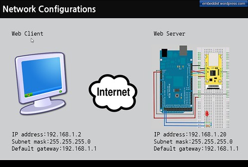
IPAddress ip(192,168,1,20);
IPAddress gateway( 192, 168, 1, 1 );
IPAddress subnet( 255, 255, 255, 0 );
// fill in your Domain Name Server address here:
IPAddress myDns(8, 8, 8, 8); // google puble dns
// Initialize the Ethernet server library
// with the IP address and port you want to use
// (port 80 is default for HTTP):
EthernetServer server(80);
void check_led_status();
// Define the LED PORT NUMBER
#define LED_PORT 53
void setup() {
// Open serial communications and wait for port to open:
Serial.begin(9600);
while (!Serial) {
; // wait for serial port to connect. Needed for Leonardo only
}
// initialize the LED PORT
pinMode(LED_PORT, OUTPUT);
// initaial value is HIGH
digitalWrite(LED_PORT, HIGH);
// initialize the ethernet device
#if defined __USE_DHCP__
#if defined(WIZ550io_WITH_MACADDRESS) // Use assigned MAC address of WIZ550io
Ethernet.begin();
#else
Ethernet.begin(mac);
#endif
#else
#if defined(WIZ550io_WITH_MACADDRESS) // Use assigned MAC address of WIZ550io
Ethernet.begin(ip, myDns, gateway, subnet);
#else
Ethernet.begin(mac, ip, myDns, gateway, subnet);
#endif
#endif
// start the Ethernet connection and the server:
server.begin();
Serial.println("WebServerControlLED");
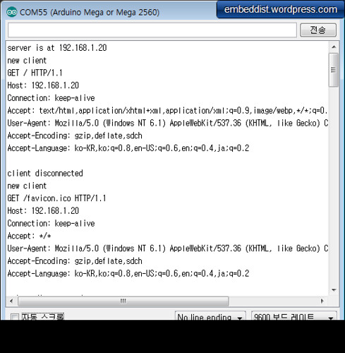
Serial.print("server is at ");
Serial.println(Ethernet.localIP());
}
void loop() {
// listen for incoming clients
EthernetClient client = server.available();
if (client) {
Serial.println("new client");
// an http request ends with a blank line
boolean currentLineIsBlank = true;
String buffer = ""; // Declare the buffer variable
while (client.connected()) {
if (client.available()) {
char c = client.read();
buffer += c; // Assign to the buffer
Serial.write(c);
// if you've gotten to the end of the line (received a newline
// character) and the line is blank, the http request has ended,
// so you can send a reply
if (c == 'n' && currentLineIsBlank) {
// send a standard http response header
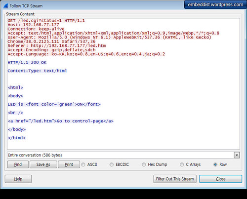
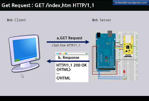
client.println("HTTP/1.1 200 OK");
client.println("Content-Type: text/html");
client.println();
//client.println("<!DOCTYPE HTML>");
client.println("<html>");
client.println("<body>");
// check the LED status
if (digitalRead(LED_PORT)>0){
client.println("LED is <font color='green'>ON</font>");
}else{
client.println("LED is <font color='red'>OFF</font>");
}
// generate the Form
client.println("<br />");
client.println("<FORM method="get" action="/led.cgi">");
client.println("<P> <INPUT type="radio" name="status" value="1">ON");
client.println("<P> <INPUT type="radio" name="status" value="0">OFF");
client.println("<P> <INPUT type="submit" value="Submit"> </FORM>");
client.println("</body>");
client.println("</html>");
break;
}
if (c == 'n') {
// you're starting a new line
currentLineIsBlank = true;
buffer="";
}
else if ( c == 'r') {
//do cgi parser for LED-On
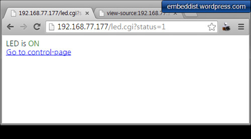
if(buffer.indexOf("GET /led.cgi?status=1")>=0){
// cgi action : LED-On
digitalWrite(LED_PORT, HIGH);
// send web-page
client.println("HTTP/1.1 200 OK");
client.println("Content-Type: text/html");
client.println();
client.println("<html>");
client.println("<body>");
// check the LED status
if (digitalRead(LED_PORT)>0){
client.println("LED is <font color='green'>ON</font>");
}else{
client.println("LED is <font color='red'>OFF</font>");
}
client.println("<br />");
client.println("<a href="/led.htm">Go to control-page</a>");
client.println("</body>");
client.println("</html>");
currentLineIsBlank = false;
break;
}
//do cgi parser for LED-Off
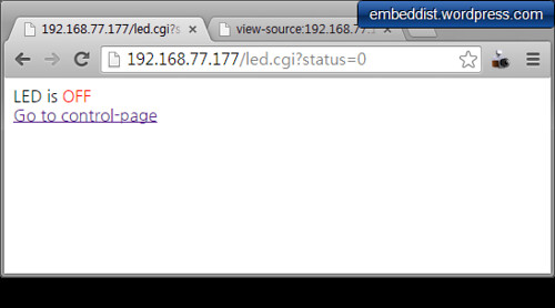
if(buffer.indexOf("GET /led.cgi?status=0")>=0){
// action : LED-Off
digitalWrite(LED_PORT ,LOW);
// send web-page
client.println("HTTP/1.1 200 OK");
client.println("Content-Type: text/html");
client.println();
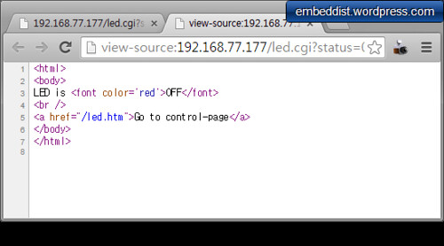
client.println("<html>");
client.println("<body>");
// check the LED status
if (digitalRead(LED_PORT)>0){
client.println("LED is <font color='green'>ON</font>");
}else{
client.println("LED is <font color='red'>OFF</font>");
}
client.println("<br />");
client.println("<a href="/led.htm">Go to control-page</a>");
client.println("</body>");
client.println("</html>");
currentLineIsBlank = false;
break;
}
}
else{ //if( c != 'r') {
// you've gotten a character on the current line
currentLineIsBlank = false;
}
}
}
// give the web browser time to receive the data
delay(1);
// close the connection:
client.stop();
Serial.println("client disonnected");
}
}
[/code]


 )
)